7 Best Magnetic Pogo Pin Connectors for OEM Buyers

Time:2026-10-20 Author:Isabella
0%

Magnetic Pogo Pin Connector technology is moving from niche charging docks into medical devices, robotics, wearables, and industrial equipment. Its appeal is practical: fast alignment, blind mating, compact packaging, and fewer exposed contacts. Yet magnetic attraction alone does not guarantee a reliable connection.

MarketsandMarkets’ 2023 Connectors Market report estimated the global connector industry at approximately USD 84 billion, with continued growth expected through 2028. The report highlights miniaturization, automation, and higher-density designs as important market drivers. These trends directly affect OEM connector decisions. A product engineer must examine contact resistance, mating cycles, magnet strength, plating quality, current capacity, and sealing performance. Small details matter. A weak spring can interrupt charging. Poor nickel or gold plating can accelerate corrosion. Misaligned magnets can damage delicate housings.

Ron Bishop, founder of Bishop & Associates and a long-time connector industry analyst, has emphasized this principle: “Connector performance is a system issue, not a component issue.” That view is especially relevant when selecting a Magnetic Pogo Pin Connector for production equipment. The connector must fit the enclosure, power architecture, cleaning process, and assembly method. Laboratory samples can perform well. Mass production may expose different weaknesses.

This guide reviews seven Magnetic Pogo Pin Connector options for OEM buyers. The comparison considers electrical performance, mechanical durability, customization, environmental protection, supply stability, and practical integration costs. No single model is perfect. Some designs offer stronger magnetic retention but less flexibility. Others reduce size but sacrifice current capacity. Careful testing remains essential.
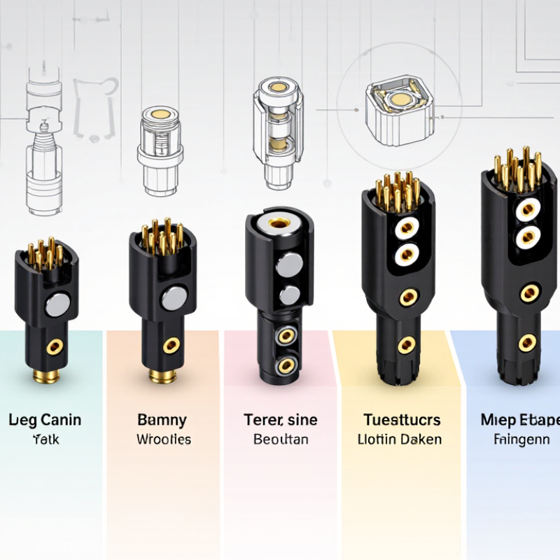
7 Best Magnetic Pogo Pin Connectors for OEM Buyers

What Are Magnetic Pogo Pin Connectors and How Do They Work?

Magnetic pogo pin connectors combine spring-loaded contacts with magnets. They create a detachable electrical and mechanical connection. Each pin contains a conductive plunger, spring, barrel, and contact tip. When two connector halves approach, magnetic force helps guide their alignment. The magnets provide attraction, not the primary electrical path. Current travels through the plated contact surfaces. A small snap can make installation easier.

During operation, the spring keeps pressure against the mating contact. This pressure helps maintain conductivity despite minor movement or vibration. Separating the halves usually requires a direct pulling force. Some designs also use different magnet orientations to prevent incorrect mating. In practical OEM testing, connection feel matters. However, a strong magnetic pull does not always mean stable electrical performance. Contact resistance, spring fatigue, and surface contamination still require measurement.

OEM buyers should review rated current, voltage, mating cycles, operating temperature, and allowable misalignment. Connector dimensions also affect housing design and assembly speed. Exposed contacts may collect dust, skin oil, or metal particles. Sealing and cleaning plans deserve attention. Thermal expansion can change contact pressure in compact devices. Designers sometimes overlook cable strain near the connector. That mistake can transfer force directly to the pins. Prototype testing should include repeated docking, vibration, twisting, and accidental side loads. Published specifications are useful, but real samples may behave differently. Keep that uncertainty visible during validation.

7 Best Magnetic Pogo Pin Connectors for OEM Buyers - What Are Magnetic Pogo Pin Connectors and How Do They Work?

What are magnetic pogo pin connectors? Magnetic pogo pin connectors combine spring-loaded electrical contacts with magnets. The magnets provide self-alignment and holding force, while the pogo pins maintain electrical contact through controlled spring compression. They are commonly used for detachable power, charging, signal, and data connections.
Comparative Guide to Magnetic Pogo Pin Connector Configurations
Rank Connector Configuration Typical Contact Count Typical Pitch Typical Current per Contact Typical Contact Resistance Typical Mating Life Best OEM Use Case How the Magnetic System Works
1 2-Pin Power Connector 2 contacts 1.27–2.54 mm 1–3 A Typically ≤50 mΩ 10,000–30,000 cycles Battery charging, portable electronics, simple DC power transfer A pair of opposing magnets attracts the two connector halves and brings the positive and negative spring contacts into alignment.
2 4-Pin Power and Ground Connector 4 contacts 1.27–2.54 mm 1–3 A Typically ≤50 mΩ 10,000–30,000 cycles Wearables, handheld devices, docking accessories, compact chargers The magnetic force guides the connector while multiple spring pins compensate for small height and angular tolerances.
3 6–8-Pin Power and Signal Connector 6–8 contacts 1.00–2.00 mm 0.5–2 A Typically ≤80 mΩ 10,000–20,000 cycles Industrial sensors, test fixtures, smart appliances, removable modules Magnets create repeatable mating while dedicated pogo pins carry power, ground, control signals, or low-speed data.
4 High-Current Magnetic Connector 2–6 contacts 2.00–3.50 mm 3–15 A Typically ≤30 mΩ 5,000–20,000 cycles Robotics, battery packs, mobile equipment, higher-power charging systems Larger-diameter spring pins and wider conductive surfaces reduce electrical resistance; magnets provide mating force but do not carry the current.
5 Sealed Waterproof Magnetic Connector 2–12 contacts 1.27–2.54 mm 0.5–5 A Typically ≤80 mΩ 5,000–20,000 cycles Outdoor equipment, medical devices, marine electronics, washdown environments The magnetic interface aligns the contacts, while elastomer seals and a controlled housing design can protect the mated interface from moisture and dust.
6 Ultra-Low-Profile Connector 2–10 contacts 0.80–1.27 mm 0.3–1.5 A Typically ≤100 mΩ 5,000–15,000 cycles Slim wearables, compact consumer devices, space-constrained assemblies Small magnets and short-stroke pogo pins enable detachable contact where board height and connector footprint must be minimized.
7 Keyed and Polarized Blind-Mate Connector 4–20 contacts 1.27–2.54 mm 0.5–3 A Typically ≤80 mΩ 10,000–30,000 cycles Replaceable modules, docking stations, industrial control panels, serviceable equipment Keying features, asymmetric magnet polarity, or mechanical guides prevent incorrect orientation while the magnets assist blind mating.
OEM selection note: The values shown are representative engineering ranges rather than universal ratings. Actual current capacity, contact resistance, mating life, magnetic holding force, environmental protection, and signal performance depend on pin diameter, spring force, plating, housing design, cable termination, thermal conditions, alignment tolerance, and the complete assembly. Waterproof ratings apply only when the connector is specifically designed, assembled, and tested for the stated protection level.

Key Selection Criteria for OEM Magnetic Pogo Pin Connectors

OEM buyers comparing the seven best magnetic pogo pin connectors should begin with the application, not the catalog image. Define voltage, continuous current, peak current, pin count, and available space. A charging dock may need six contacts, while a wearable device may need only two. Measure the compressed and extended pin positions carefully. Small alignment errors can interrupt charging.

Contact reliability depends on more than magnet strength. Check spring travel, contact resistance, plating material, cycle life, and tolerance control. A connector with strong magnets may still wear quickly if its pins scrape during docking. Gold-plated contacts usually resist oxidation, but coating thickness and testing evidence matter. Ask for test conditions, not only impressive cycle numbers. Use a design with mechanical guidance when the product will be connected thousands of times.

Environmental performance deserves equal attention. Review operating temperature, humidity resistance, dust protection, and resistance to sweat or cleaning chemicals. Magnetic debris can collect around exposed contacts. That detail is easy to miss. Request samples and perform repeated docking tests with real housings, cable loads, and slight user misalignment. Prototype results often differ from laboratory claims. I have seen promising connectors fail because the magnet pulled unevenly. Allow space for service access and replacement. Also confirm consistent supply, inspection records, and traceable material documentation before approving mass production.

7 Best Magnetic Pogo Pin Connectors for OEM Buyers

Key Selection Criteria for OEM Magnetic Pogo Pin Connectors

The chart presents a practical OEM evaluation model using weighted criteria. Electrical performance, mechanical durability, environmental protection, magnetic retention, manufacturability, customization flexibility, and total cost are commonly reviewed when selecting magnetic pogo pin connectors. The percentages represent recommended evaluation weights rather than data from any specific company or brand.

Seven Leading Magnetic Pogo Pin Connector Options for OEM Buyers

OEM buyers can choose among seven leading magnetic pogo pin connector options, each suited to a different product constraint. A compact two-pin design fits wearable devices with limited board space. A higher-current multi-pin version supports charging docks and industrial terminals. A waterproof sealed option helps outdoor equipment resist dust and splash exposure. A recessed-contact model reduces accidental shorting during handling. A spring-guided alignment type improves connection when users dock devices quickly. A low-profile side-entry design supports thin enclosures and tight cable paths. A custom contact arrangement can combine power, data, and grounding in one interface.

Selection should begin with measurable requirements, not appearance. Check rated current, contact resistance, mating cycles, magnetic force, and operating temperature. Verify the pin stroke under real compression conditions. Small tolerances can create intermittent signals. During prototype reviews, I have found that magnets sometimes attract metal debris near exposed contacts. That detail is easy to miss. It matters in workshops and field equipment.

Request samples with production-grade plating and inspect them after repeated mating tests. Test misalignment, vibration, sweat, cleaning agents, and cable tension. A connector may pass a laboratory check yet fail after daily docking. I once underestimated the effect of side loading on spring pins. The lesson was expensive. Ask for drawings, material data, quality records, and traceable test results before approving tooling. Also confirm whether the supplier can maintain pin height consistently across batches. Seven options may look similar, but their failure risks are not equal.

Comparing Connector Performance, Durability, and Customization

For OEM buyers, the seven best magnetic pogo pin connectors should be compared by performance, durability, and customization. A strong connector maintains stable contact during vibration, repeated mating, and slight alignment errors. Measure contact resistance under load, not only at room temperature. Current capacity also depends on pin size, spring force, housing material, and cable length. Small differences can affect charging speed and signal quality.

Durability requires more than a high mating-cycle claim. Examine spring fatigue, plating thickness, magnet retention, and resistance to dust or moisture. In production testing, connectors should face repeated mating, side loading, temperature changes, and vibration. A sealed design may protect better, but sealing can increase mating force. That trade-off is easy to overlook. Test real assemblies, not isolated samples.

Customization can include pin count, magnetic polarity, cable exit direction, mounting holes, over-mold shape, and contact spacing. Mechanical drawings should define tolerances clearly. Electrical options may include power contacts, signal contacts, grounding paths, or keyed arrangements. One practical concern remains: custom tooling can raise minimum order quantities and extend development time. Prototype fit may also hide long-term wear. Review sample failures honestly before approving mass production.

How to Choose the Right Connector for Your OEM Application

7 Best Magnetic Pogo Pin Connectors for OEM Buyers

How to Choose the Right Connector for Your OEM Application

Choosing a magnetic pogo pin connector starts with the product’s real operating conditions. Define contact current, voltage, mating cycles, and available space. A connector for a handheld scanner may need a compact body and strong alignment. A charging dock may need higher current capacity and better heat control. Do not select by appearance alone.

Check the pin structure, spring force, plating, and magnet strength. Gold-plated contacts usually resist oxidation during repeated use. However, thicker plating can increase cost. Review the rated current under actual temperature conditions, not only laboratory figures. Ask for test data covering vibration, dust, humidity, and salt exposure. These details reveal more than a polished specification sheet.

Mechanical tolerance also deserves attention. Misalignment can damage pins or create unstable charging. Use guide features when the enclosure allows them. Measure the magnetic pull force after installing nearby steel parts, because surrounding materials can change performance. A common mistake is ignoring cable strain at the connector exit. Add bend relief and test the assembly during repeated docking. No connector is perfect. A slightly larger design may offer better reliability, while a smaller one may simplify packaging. Build sample units early, inspect worn contacts, and revise the design before tooling.

FAQS

What is a magnetic pogo pin connector?

It combines spring-loaded electrical contacts with magnets. The magnets guide alignment and provide attraction. The plated contact surfaces carry current.

How does the connection remain electrically stable?

An internal spring pushes each contact against its mating surface. This pressure helps resist minor movement and vibration. Contact resistance still needs testing.

Do stronger magnets guarantee better performance?

No. Strong magnetic pull does not ensure stable conductivity. Spring fatigue, dirt, and surface wear can still cause failures.

What should OEM buyers check before selection?

Review current, voltage, mating cycles, temperature, dimensions, and allowable misalignment. Check the pin stroke under real compression conditions.

Which connector design suits compact wearable equipment?

A compact two-pin design can fit limited board space. Low-profile side-entry versions suit thin enclosures. Packaging may become easier.

Which design supports higher-current charging equipment?

A multi-pin design may support charging docks and industrial terminals. Confirm heat control and rated current at actual temperatures.

How can exposed contacts create problems?

Dust, skin oil, and metal particles may collect on exposed surfaces. Contamination can increase contact resistance. Cleaning plans matter.

What mechanical tests should prototypes include?

Test repeated docking, vibration, twisting, misalignment, and side loads. Also test cable tension near the connector exit. Side loading is easy to underestimate.

Why should nearby metal parts be tested?

Surrounding steel can change magnetic pull and alignment. It may also attract debris near the contacts. Test the assembled product, not only loose parts.

How can designers improve long-term reliability?

Add guide features and cable bend relief where possible. Inspect worn contacts after repeated docking. A larger connector may work better, though it uses more space.

Conclusion

Magnetic Pogo Pin Connector systems combine spring-loaded electrical contacts with magnetic alignment, enabling fast, reliable connections without traditional screws, clips, or complex insertion mechanisms. For OEM buyers, the right solution should be evaluated by contact stability, current and voltage capacity, mating cycles, magnetic holding force, size, thermal performance, environmental resistance, and ease of integration. Proper plating and contact materials can also improve conductivity and reduce wear over time.

This guide reviews seven leading connector options from a practical OEM perspective, comparing their performance, durability, installation flexibility, and customization potential. It explains how different designs suit applications such as compact electronics, charging interfaces, modular equipment, and products requiring frequent connection and disconnection. By matching connector specifications with operating conditions, mechanical constraints, production volume, and certification needs, engineers can select a Magnetic Pogo Pin Connector that delivers dependable performance, efficient assembly, and long-term value.


Isabella

Isabella

Isabella is a dedicated marketing professional with a sharp focus on driving brand growth and engagement through strategic content creation. With an extensive background in digital marketing, she combines her passion for storytelling with her keen understanding of industry trends to deliver......