Choosing the right High Current Magnetic Connector begins with understanding the real electrical load, not just the advertised current rating. The International Energy Agency reported nearly 14 million electric car sales in 2023. This growth increases demand for compact, durable, and serviceable power connections. Similar pressures appear in robotics, battery storage, medical equipment, and industrial automation.
A reliable selection process examines continuous current, peak current, voltage, contact resistance, temperature rise, and mating cycles. It also checks cable size and enclosure conditions. A connector carrying 40 amperes in a cool laboratory may perform differently inside a sealed battery cabinet. Grand View Research identifies continued expansion in the global electrical connectors market, supported by electrification and automation. That trend matters, but market growth does not guarantee product quality. Datasheets can look convincing.
I recommend comparing independent test evidence with IEC 61984 safety principles and relevant UL requirements, such as UL 1977 where applicable. Look for documented thermal testing, short-circuit protection, magnetic retention strength, polarization, and resistance to dust or moisture. In practical testing, measure connector temperature after sustained operation. Inspect the contacts after repeated connection cycles. A small voltage drop can become significant heat. No connector is perfect. Engineers sometimes prioritize peak current and overlook daily handling, misalignment, or accidental side loads. The best High Current Magnetic Connector balances electrical performance, mechanical safety, service life, and installation reality. That balance deserves careful review before purchasing.
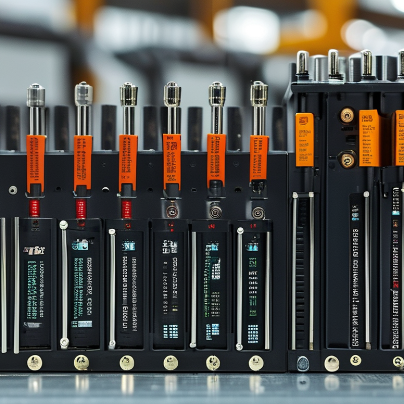
Choosing a high-current magnetic connector starts with numbers, not housing shape. Record the load’s continuous current, peak current, operating voltage, and duty cycle. A motor may draw 8 A normally but reach 24 A during startup. That short surge can damage contacts or trigger protection. Measure it with a calibrated meter or oscilloscope when possible. Do not rely only on the label. Real loads vary with temperature, cable length, and mechanical resistance. Write down the highest credible value, not just the average.
Calculate power with P = V × I, then check whether the connector can carry that power without excessive heating. For example, 12 V at 15 A equals 180 W, but contact resistance still creates local heat. Even a small resistance matters at high current. Ask for continuous and peak ratings under stated ambient conditions. A connector rated at 20 A in a cool test may need derating inside a sealed enclosure. Check voltage drop across the mated contacts, especially for low-voltage systems. A 0.2 V loss can affect a 5 V circuit more than a 48 V circuit. Verify polarity, isolation, and required make-and-break behavior. Magnetic alignment does not replace overcurrent protection.
Test it under real conditions. Run the connector at the intended load for several hours, then measure terminal temperature. I have found quick bench tests reassuring, yet incomplete. Cable flexibility and repeated mating can change results. Leave honest margin. The first calculation is rarely perfect.
Use the electrical requirements first, then verify contact temperature rise, mating-cycle life, environmental sealing, cable size, and safety certification for the intended application.
| Application Profile | System Voltage | Continuous Current | Peak Current (Up to 10 s) |
Calculated Power (V × A) |
Recommended Design Margin | Suggested Contact Arrangement | Key Connector Requirements |
|---|---|---|---|---|---|---|---|
| Portable DC equipment | 12 V DC | 20 A | 30 A | 240 W continuous 360 W peak |
Choose a connector rated for at least 25 A continuous and 40 A peak. | 1 positive power contact + 1 negative power contact | Polarized housing, finger-safe contacts, low-profile magnetic coupling, and strain relief for flexible cable. |
| Robotics and mobile machinery | 24 V DC | 40 A | 60 A | 960 W continuous 1,440 W peak |
Allow approximately 25% current headroom above the maximum continuous load. | 2 power contacts; optional signal contacts for interlock or status | High-cycle mating design, vibration resistance, keyed polarity, and contacts sized for the selected cable gauge. |
| Battery-powered industrial tools | 36 V DC | 50 A | 80 A | 1,800 W continuous 2,880 W peak |
Select a connector with a continuous rating of at least 62.5 A and a peak rating of at least 100 A. | 2 power contacts; auxiliary contacts may support temperature or battery-status sensing | Low contact resistance, secure alignment, arc-reduction strategy, and robust cable retention. |
| Electric vehicle auxiliary systems | 48 V DC | 50 A | 100 A | 2,400 W continuous 4,800 W peak |
Use at least 20% continuous-current margin; verify peak withstand capability separately. | 2 power contacts plus optional low-voltage signal contacts | Touch-safe construction, high-voltage DC spacing, environmental sealing, vibration resistance, and interlock compatibility. |
| Telecom and backup-power distribution | 48 V DC | 100 A | 125 A | 4,800 W continuous 6,000 W peak |
Apply a minimum 25% thermal margin and confirm the rating at the actual ambient temperature. | Multiple parallel power contacts may be required for current sharing | Continuous-duty thermal performance, low milliohm contact resistance, serviceability, and clear polarity identification. |
| Industrial battery storage | 96 V DC | 150 A | 225 A | 14,400 W continuous 21,600 W peak |
Connector target: at least 187.5 A continuous and 281 A peak, subject to thermal validation. | 2 or more power contacts; separate protective-earth or interlock provisions as required | High-voltage DC insulation, touch protection, pre-charge or switching provisions, locking retention, and certified creepage and clearance. |
| High-voltage DC power module | 400 V DC | 100 A | 150 A | 40,000 W continuous 60,000 W peak |
Do not select by current alone; verify insulation system, DC switching behavior, fault rating, and applicable safety standards. | 2 high-voltage power contacts with optional interlock and pre-charge contacts | Finger-safe architecture, high creepage and clearance, HVIL support, arc-control design, shielding, and qualified high-voltage testing. |
Pogo-pin contacts suit compact devices and frequent mating. Flat spring contacts usually support higher currents. Hybrid designs carry power and signals together. Choose based on space, vibration, and connection frequency.
No. Check both continuous and peak current ratings. A connector rated for 30 amps briefly may overheat during continuous operation. Review the derating chart and measure heat during actual use.
Run the expected load for about thirty minutes. Measure temperature near the contacts and housing. Warm plastic may indicate high resistance or undersized conductors. I would not rely on touch alone.
Small resistance creates significant heat at high current. Measure resistance in milliohms and check voltage drop after repeated mating cycles. Clean-looking contacts may already be weakening.
Look for polarity control, insulated contacts, strain relief, and short-circuit protection. Confirm voltage and temperature limits. Prevent exposed terminals from touching accidentally. Magnetic attraction is not enough.
Not always. Magnetic connections can separate during pulling, vibration, or equipment movement. Use a locking design when accidental disconnection creates risk. This detail is easy to underestimate.
Dust, moisture, coolant, and vibration can increase contact resistance. Consider sealing, corrosion resistance, and operating temperature. Laboratory protection ratings may not match a dirty workshop. Real conditions matter.
Verify polarity, pin arrangement, cable gauge, flexibility, dimensions, and alignment tolerance. Check whether ratings apply to one contact or the entire assembly. A perfect rating is useless if the connector fits poorly.
Inspect contacts, housings, and cables regularly. Clean gently and check temperature after heavy use. Record heat marks, loose contacts, and intermittent power. Replace parts by operating hours, not guesswork.
Focusing only on the largest current number. I made that mistake and underestimated connector heating. A lower-rated option may perform better with cooling, stronger strain relief, and easier maintenance.
Choosing the right High Current Magnetic Connector begins with clearly defining your electrical requirements, including continuous and peak current, operating voltage, power demand, and expected duty cycle. These factors help determine the connector’s appropriate current rating, contact arrangement, magnetic coupling strength, and overall electrical configuration. It is also important to consider whether the application requires a simple detachable connection, a polarized design, or a solution that supports frequent connection and disconnection.
Next, evaluate contact materials, connection structure, thermal performance, and resistance to heat buildup during operation. A reliable connector should provide stable contact pressure, efficient heat dissipation, and minimal voltage drop. Safety features such as overcurrent protection, secure alignment, insulation, and resistance to accidental short circuits should also be reviewed. Assess durability against vibration, dust, moisture, and repeated use, while confirming compatibility with cables, devices, and installation conditions. Finally, compare technical specifications, testing data, maintenance requirements, and total cost to select the connector that offers the best balance of performance, safety, reliability, and long-term value for your application.

 Rongqiangbin