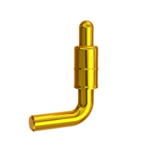
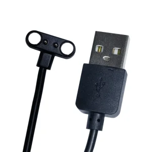
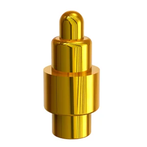
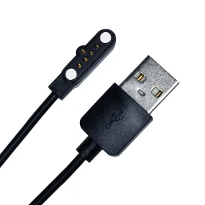
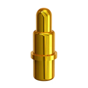
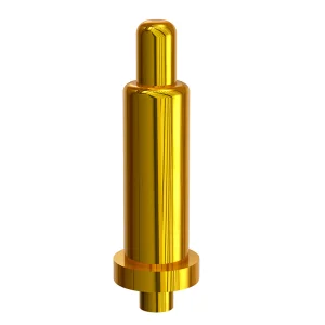
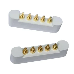
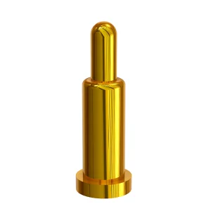
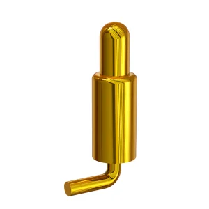
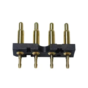
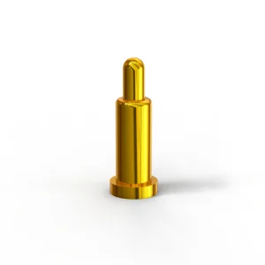
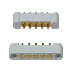
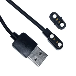
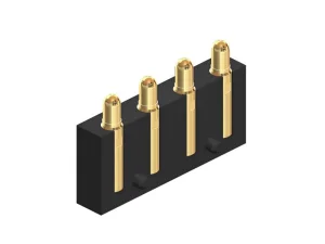
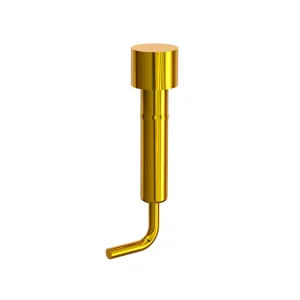
Explore our production-grade Pogo Pin arrays and custom magnetic cable assemblies optimized for seamless PCB routing and high-reliability mechanical connection.
Essential mechanical considerations, surface mount (SMT) rules, through-hole guidelines, and post-assembly quality controls for industrial hardware designers.
Deploy solder stencils with a recommended thickness of 0.12mm to 0.15mm. Ensure paste volume is strictly regulated to prevent solder climbing up the plunger barrel, which can cause spring seizure or electrical opens.
Utilize precise drill dimensions matching the pogo pin tail outer diameter plus a clearance of 0.1mm. High capillary action during wave soldering must be mitigated by using anti-wicking structural barriers on the tail.
Specify interference fit tolerances on specialized FR4 or plastic housing cavities. A standardized press-fit configuration typically mandates a retention force of 15-30 Newtons per contact to ensure long-term stability.
When installing Mill-Max equivalent pogo pins, managing the thermal gradient is critical to protect internal springs (often beryllium copper or stainless steel) from losing their mechanical temper. Standard lead-free SAC305 profile parameters should be adhered to:
Predicting high-frequency, high-current miniaturization trends in spring-loaded contact technologies.
Modern wearables, VR/AR modules, and high-frequency communication cards demand smaller footprints without sacrificing electrical performance. The current technology roadmap dictates a push toward 0.3mm center-to-center pitch, which challenges traditional mechanical lathe constraints. Advanced laser manufacturing and hybrid alloy plungers are replacing traditional brass components to yield high durability and ultra-low internal resistance.
Concurrently, high-current charging requirements (such as fast-charging USB-PD and EV auxiliary interfaces) require individual pogo pins to carry up to 15A - 30A continuously. Internal designs now leverage specialized gold-plated bias-cut plungers and internal ball bearings to minimize contact resistance fluctuate during continuous dynamic movements.
How high-reliability spring-loaded connectors solve core application challenges across key verticals.
Sweat resistance and skin-contact compatibility require specialized biocompatible gold-plating (up to 50u") and custom sealing configurations. Our Pogo Pin solutions ensure reliable charging interfaces for devices exposed to moisture, salt spray, and daily skin contact.
In medical testing pods and wearable sensors, signal integrity is critical. Pogo pin blocks enable low contact force, reliable high-mating cycles, and quick-disconnect operations, facilitating reliable cleaning and decontamination routines.
Vehicle vibrations demand robust contact interfaces. Utilizing custom heavy-duty pogo pin connectors guarantees reliable power and sensor routing within LiDAR arrays, cabin cameras, and battery monitoring modules under thermal shock.

Founded in February 2011 and headquartered in Songgang Street, Shenzhen—the core of the Guangdong-Hong Kong-Macao Greater Bay Area—Rongqiangbin has established itself as an industry leader in high-precision connector technology. Our specialized focus spans the complete lifecycle of POGO PIN (spring thimble) design, research and development, high-volume production, and global commercial distribution.
Adhering to the core philosophy of "customer first, integrity first," we back our manufacturing processes with a robust Quality Management System. The company is certified to the international authoritative ISO9001:2015 standard, maintaining a dedicated quality assurance framework that guarantees compliance with environmental protection and strict electrical performance standards worldwide.
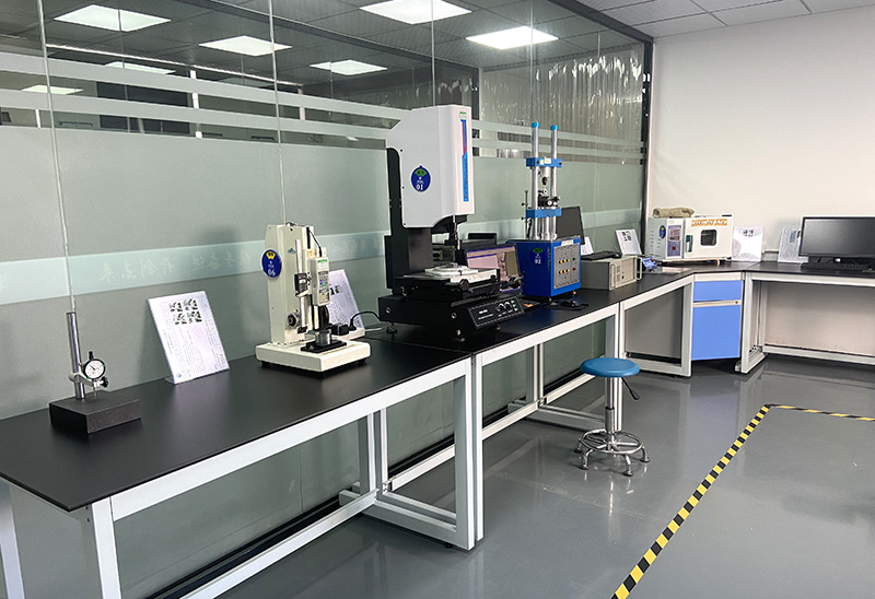
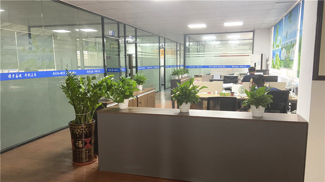
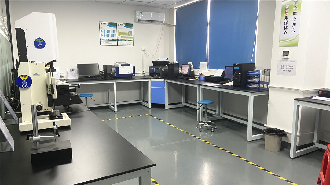
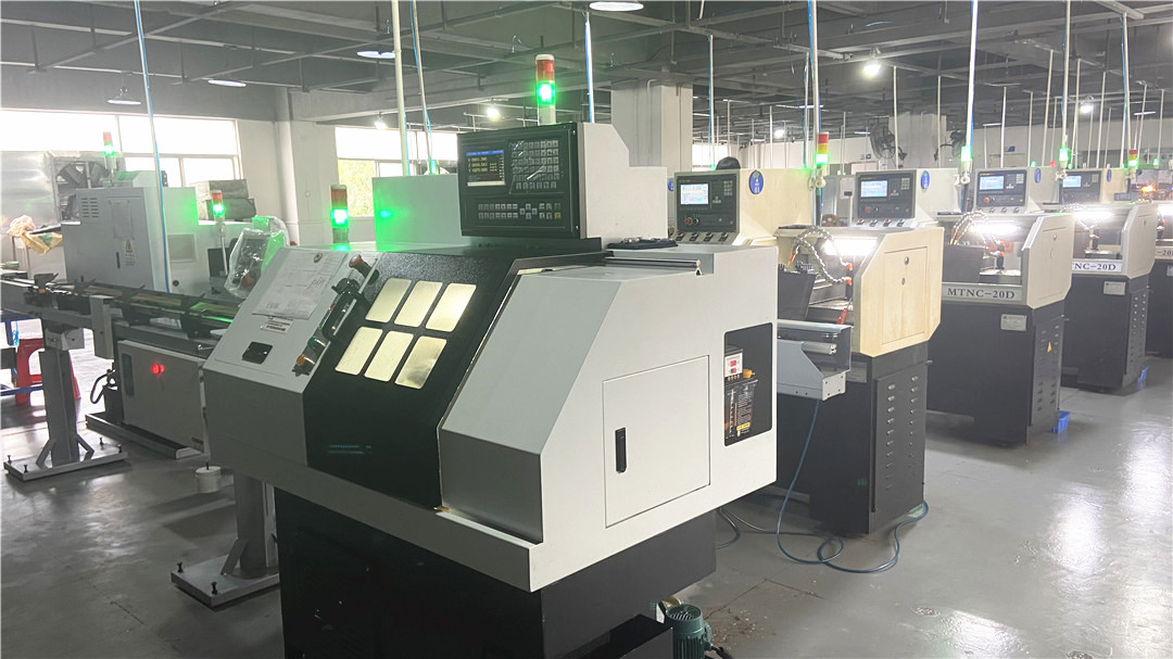
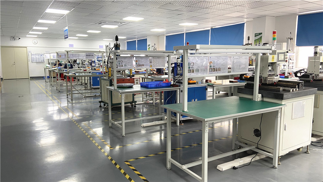
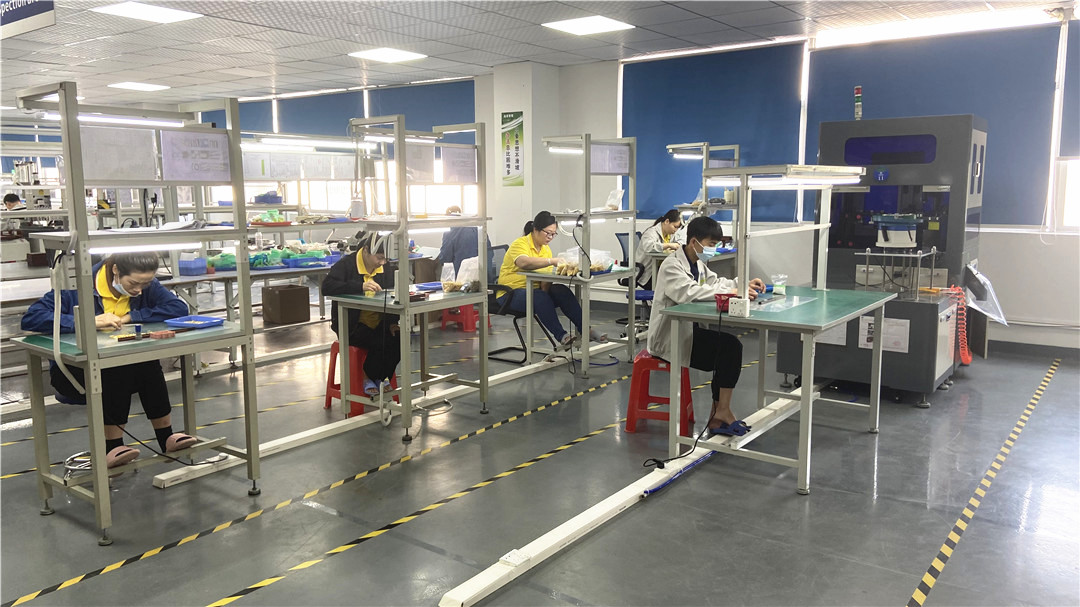
Explore our state-of-the-art facility featuring automated CNC lathes, high-volume assembly lines, and comprehensive quality control labs.
By integrating advanced automatic assembly systems with high-speed Japanese CNC lathes, our facility is optimized for both precision and volume. We achieve high repeatability for micro-plunger dimensions and run automated visual inspection systems (AOI) to verify pin heights, outer diameters, and spring forces under load. This integrated approach ensures consistent quality and fast production times for high-volume orders.
Our client base includes industry leaders such as Honeywell, Samsung, SIEMENS AG, ZTE, 360, QCY, HAYLOU, Shanghai Laimu, Luxshare Group, Aoni Electronics, and Amphenol Group. This track record reflects our capability to deliver reliable engineering solutions, on-time delivery, and technical support across complex supply chains.
Our products are integrated across diverse application areas, including Smart wearables (wristbands, smart watches), mobile phone antennas, laptops, Bluetooth headsets, learning machines, game consoles, GPS satellite navigation systems, aerospace electronics, medical diagnostic equipment, and ruggedized military communications devices.

Detailed structural parameters, material configurations, and customization options for international procurement managers.
| Specification Parameter | Standard Range Offered | Custom (ODM/OEM) Capability |
|---|---|---|
| Plunger Plating | 0.1μm to 1.25μm (4u" to 50u") Gold plating over Nickel | Platinum, Palladium-Nickel, Hard Gold alloys |
| Spring Force | 30g to 150g (Nominal compression stroke) | Heavy-duty contacts up to 500g mechanical force |
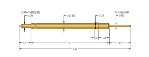
| Body Diameter | 0.5mm to 3.0mm barrel diameters | Ultra-miniaturized down to 0.3mm pin body |
| Housing Materials | HTN, LCP, PA46, PA9T (High-temp thermal polymers) | Custom injection-molded frames with magnetic polarity keys |
| Maximum Current | 2A to 5A continuous duty per pin | Up to 15A per channel (parallel arrays) |
| Compliances | RoHS, REACH, Halogen Free, ISO9001:2015 | Automotive IATF 16949 & ISO 13485 (Medical) alignment |
Securing stable international deployment through rigorous global standards and customized logistics.
All finished products and raw materials are tested for compliance with EU RoHS 2.0, REACH, and Halogen-Free directives. We guarantee safe application in both consumer electronics and hazardous industrial environments.
To support high-speed pick-and-place SMD assembly lines, we provide customized tape-and-reel packaging conforming to EIA-481 standards. This ensures high placement accuracy and low pick failure rates.
Our engineering team delivers full 2D layout drawings, 3D STEP files, and simulation data to verify mechanical stress profiles and signal loss parameters before tooling fabrication begins.
Technical and mechanical answers to common questions about installing and procuring pogo pins.
Explore our specialized portfolio of custom spring contacts, waterproof adapters, and high-density interface connectors.
 Rongqiangbin