OEM Pogo Pin Design Guide Manufacturers & Suppliers

Precision Engineering, Custom Connector Configurations, and Global Supply Chain Excellence for Strategic Procurement Managers

Featured High-Precision Connectors (Series I)

Engineered for robust mechanical mating cycles and optimal electrical performance in smart electronics.
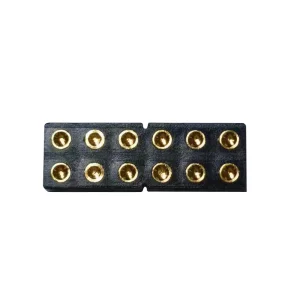
OEM 12 pin Pogo Pin Connector

OEM 12 pin Spring Loaded Pogo pin Connector Plain Base Type

Explore Specifications →
High-Quality Soldering Wire Spring Contacts Pogo Pins

High-Quality Soldering Wire Spring Contacts Pogo Pins Manufacturers

Explore Specifications →
OEM SMT/SMD Pogo Pin Keyboard Suppliers

OEM SMT/SMD Pogo Pin Keyboard Suppliers, Factory

Explore Specifications →
Custom SCFB038 Supplier

Custom SCFB038 Supplier, Precision Machined Components

Explore Specifications →
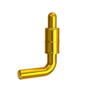
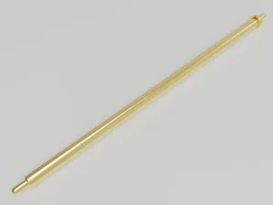
Custom Bending Type Spring Pogo Pins

Custom Bending Type Spring Pogo Pins Manufacturers, Supplier

Explore Specifications →
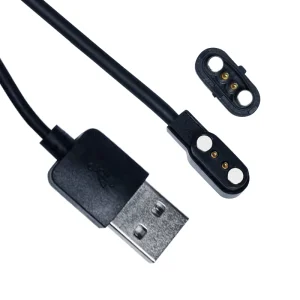
OEM 2 pin Pogo Pin Magnetic USB Charger Cable

OEM 2 pin Pogo Pin Black Magnetic Data USB Charger Cable

Explore Specifications →
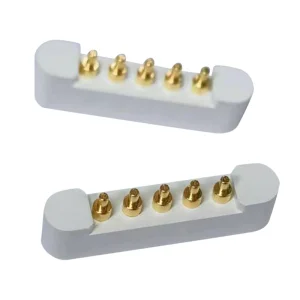
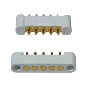
High-Quality 5 Pin Spring Loaded Pogo pin Connector

High-Quality 5 Pin Spring Loaded Pogo pin Connector Manufacturers

Explore Specifications →
OEM 5 Pin Waterproof Pogo pin Adapter Connector

OEM 5 Pin Waterproof Pogo pin Adapter Connector Female Factory

Explore Specifications →

1. Introduction to Custom Pogo Pin Connector Engineering

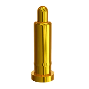
Pogo pins, also recognized as spring-loaded contacts or spring thimbles, represent the peak of high-reliability interconnect technology. Providing low contact resistance, continuous current capability, and exceptional durability in space-constrained layouts, they are preferred components across aerospace, defense, consumer electronics, and medical diagnostics industries. As a premier OEM Pogo Pin Manufacturer, Shenzhen Rongqiangbin Electronic Hardware Co., Ltd. delivers customized contact solutions tailored to strict specifications.

Developing a custom pogo pin array requires a deep understanding of electrical, mechanical, and materials engineering. Because these pins rely on a dynamic internal spring mechanism, minor deviations in dimensional tolerance, spring rate, or plating material can result in contact degradation, signficant voltage drops, or premature field failure. This guide serves as a practical blueprint for electronics engineers seeking to optimize their contact designs for manufacturability, cost efficiency, and long-term lifecycle reliability.

2011 Established Year
ISO 9001 Certified Quality
100K+ Mating Cycles Life
<30mΩ Low Resistance

2. Core Components of a Pogo Pin

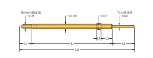
A standard spring-loaded contact consists of three distinct components. Modifying each component allows engineers to adjust the connector to handle specific mechanical and environmental pressures:

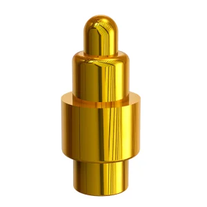
  • The Plunger (Piston): The moving contact element that interfaces directly with the target contact pad on the mating PCB or component. Plunger design typically dictates electrical performance and contact stability.
  • The Barrel (Body): The cylindrical housing containing the spring and plunger. The barrel acts as the structural mounting body and coordinates the mechanical guidance of the plunger.
  • The Internal Spring: The energy-storage engine that provides continuous normal force. Mechanical force characteristics, working travel limits, and resistance to environmental fatigue depend entirely on spring geometry and alloy composition.

Key Design Configurations: Choosing the Plunger Tail Style

The interior contact design between the plunger base and the barrel base influences current carrying limits and mechanical consistency. The three most common configurations are:
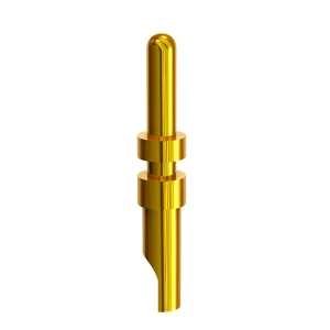
  • Back-Drill Design: The plunger is hollowed at the base to accommodate a longer spring. This allows designers to minimize the overall length of the pogo pin without compromising spring travel. It is highly suitable for thin smart wearable structures.
  • Bias-Cut (Slanted Base) Design: The bottom of the plunger is cut at an angle. The lateral force generated by the slant ensures continuous side-contact between the plunger and the inner barrel wall, bypassing the spring's high electrical resistance and offering stable current delivery.
  • Ball Insert (Insulator) Design: A tiny ceramic or stainless steel ball is placed between the plunger and spring. This design blocks current from flowing through the spring, ensuring a direct pathway through the low-resistance barrel. Ideal for high-speed signal lines and high-current power channels.
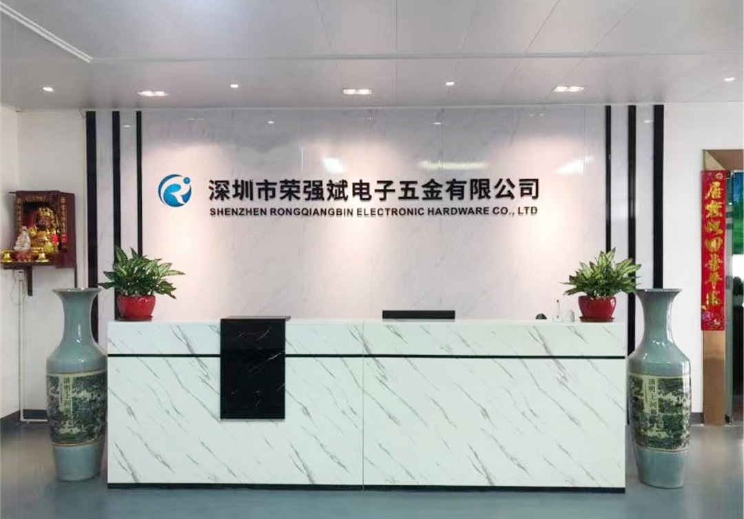
Rongqiangbin Manufacturing Facility

3. Materials Science and Advanced Electroplating

To sustain optimal conduction and prevent thermal runaway, pogo pin components require precision plating materials. The base metal must supply excellent mechanical stability, while the external plating must resist galvanic oxidation, corrosion, and wear.

Component Base Material Options Plating Specifications Key Performance Characteristics
Plunger Brass (C3604) or Beryllium Copper (BeCu) Gold (Au) over Nickel (Ni) (0.1μm - 1.25μm Au) High mechanical strength, wear resistance, low contact resistance.
Barrel Brass (C3604) or Phosphor Bronze Gold (Au) over Nickel (Ni) (Min 0.1μm Au) Excellent machinability, high structural integrity, corrosion protection.
Spring Stainless Steel (SUS304) or Music Wire Gold (Au) Plated (Flash Au) Fatigue resistance, high spring force retention, thermal limits to 120°C.

Gold Plating Optimization: For high-cycle consumer electronics (e.g., smart watch charging terminals), a gold thickness of 0.25μm to 0.5μm is recommended. In harsh marine, industrial, or medical environments where corrosion risks are elevated, plating thickness can be scaled up to 1.25μm or supplemented with a Palladium-Nickel (Pd-Ni) diffusion barrier.

4. Mechanical and Electrical Design Tolerances

When drafting your board layout and integration drawings, several key mechanical properties must be balanced to secure reliable electrical pathways:

  • Pitch Layout: Standard pogo pin spacing ranges from 1.0mm to 2.54mm. Custom micro-pitch pins can scale down to 0.4mm pitch for high-density semiconductor test probes.
  • Working Stroke vs. Full Stroke: A design should never press the pogo pin to its absolute mechanical bottom (full stroke). The nominal working stroke should sit at roughly 60% to 80% of the maximum stroke limit to prevent permanent spring deformation.
  • Normal Force Target: A typical contact force of 30g to 120g is necessary to penetrate surface oxides and dust. Lower forces risks intermittent signal dropouts; excessive force accelerates mechanical wear of the mating pad.

5. About Shenzhen Rongqiangbin Electronic Hardware Co., Ltd.

Founded in February 2011 in Songgang Street, Shenzhen, within the highly competitive Guangdong-Hong Kong-Macao Greater Bay Area, our company has grown from a specialized workshop into an international manufacturer of pogo pin connectors.

Our core operation focuses on the research, development, production, and sales of high-performance spring-loaded contacts. By adhering to the principles of "customer first, integrity first", we have nurtured a robust technical engineering team and formed long-term cooperative partnerships with several global industry leaders.

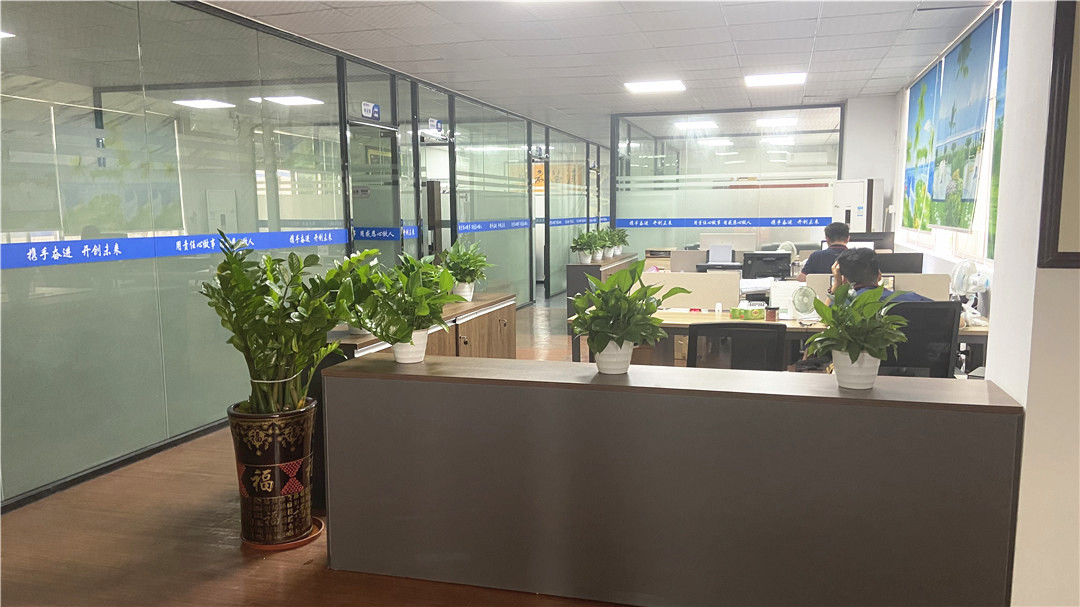
Our facility holds the ISO9001:2015 international quality management system certification. Backed by rigorous material traceability and a strict environmental management protocol, we deliver environmentally compliant solutions that meet global standards like RoHS and REACH.

Our enterprise portfolio includes collaborations with prominent global brands, including Honeywell, Samsung, SIEMENS AG, ZTE, 360, QCY, HAYLOU, Shanghai Laimu, Luxshare Group, Aoni Electronics, and Amphenol Group.

Our Corporate Vision: Committed to being an excellent POGO PIN manufacturer for both quality and cost on home and abroad, and leading connector technology development.

6. Precision Machining and Quality Control Infrastructure

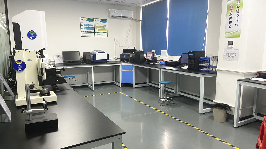
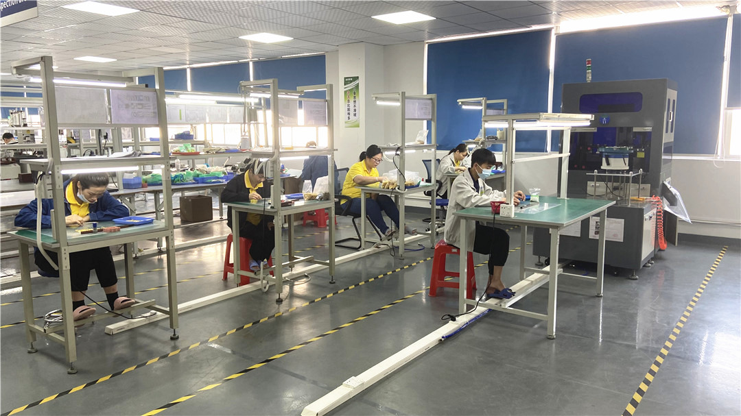
Maintaining tight mechanical tolerances requires top-tier production and test systems. Our factory features advanced CNC lathe systems, automated assembly lines, and a dedicated testing lab. Every production batch undergoes comprehensive mechanical and electrical checks before dispatch.
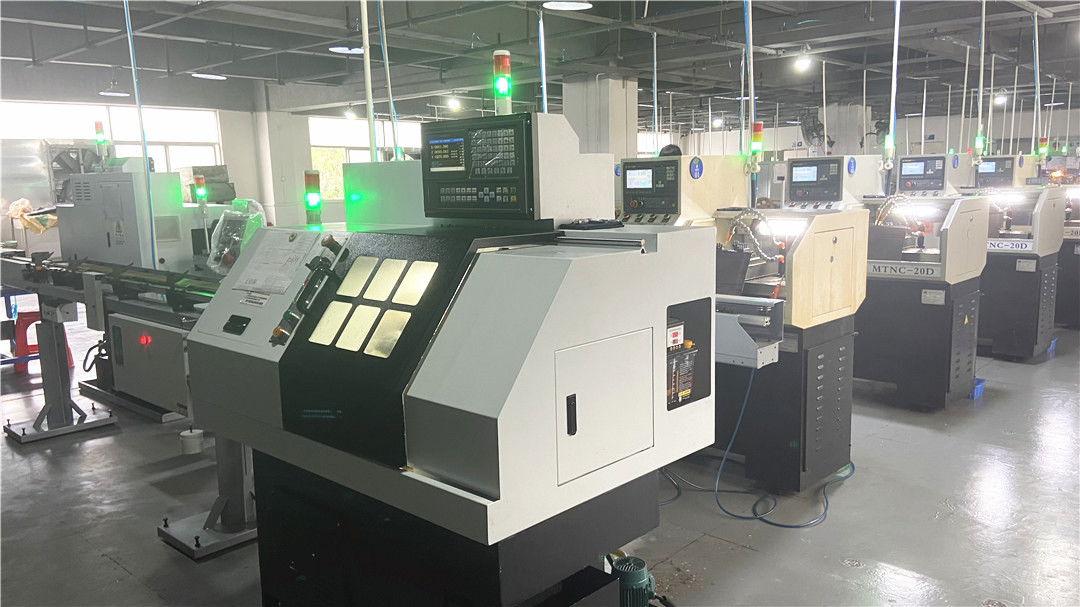
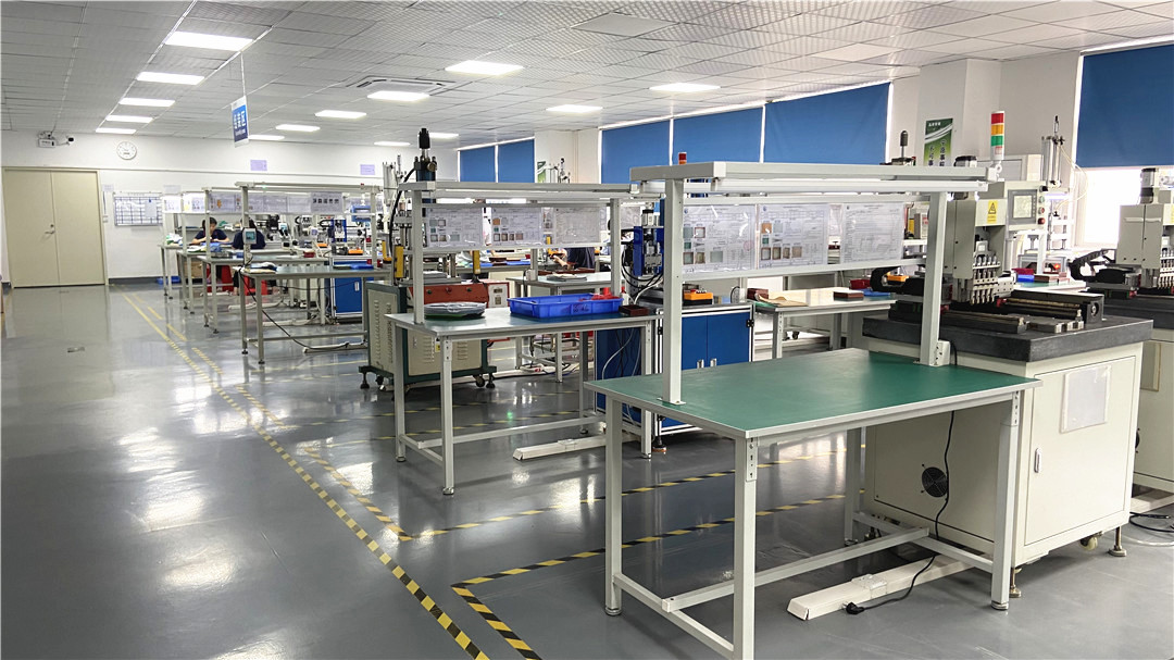
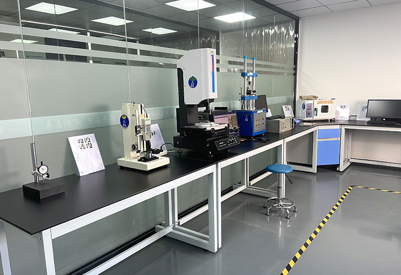
With an emphasis on "excellent quality, intimate service", we focus on generating customer-centric value. Our QA lab utilizes specialized instruments, including X-Ray Plating Thickness Analyzers, Durability Life Testers, Force-Stroke Diagram Testers, and Salt Spray Chambers, to guarantee that every pin matches its specification sheet.

7. Supply Chain Advantages of Shenzhen-Based Manufacturing

Shenzhen remains the global capital of electronics and precision hardware manufacturing. Procuring pogo pins directly from Rongqiangbin offers distinct strategic advantages:

  • Raw Material Proximity: Shenzhen's location in the Greater Bay Area ensures rapid access to high-quality brass, copper, spring wire alloys, and advanced industrial plating services.
  • Agile Prototyping: Our design engineers can translate schematic files into physical samples within 3 to 5 business days, accelerating design-validation stages.
  • Advanced CNC Machining: With high-speed Japanese Star and Citizen CNC lathe systems, we achieve tight mechanical tolerances down to ±0.005mm.
  • Integrated Assembly: Vertical integration from lathe machining to plating and final packaging allows us to optimize production costs and maintain competitive pricing.

8. Global Procurement, Compliance, and Local Support

We serve hardware engineering teams and procurement offices across North America, Europe, and Asia. Our processes align with major international requirements, including:

  • RoHS & REACH Compliance: All materials used in our pins are free of hazardous substances and certified for eco-sensitive consumer applications.
  • Global Logistics & Customs Integration: We offer DAP, CIF, FOB, and DDP shipping configurations, ensuring direct transit and custom clearance to your regional warehouse.
  • Quality Audits: We support physical and digital factory audits to review our assembly standards and quality management protocols.

9. Target Industry Applications

Thanks to their mechanical versatility and high-density pitch configurations, pogo pin assemblies are employed across diverse product fields:

  • Smart Wearable Devices: Compact charging pins for fitness wristbands, smartwatches, and true wireless (TWS) earbuds.
  • Mobile Devices & Computing: SMT internal connectors for antennas, laptop display hinges, and magnetic keyboard interfaces.
  • Medical Technology: Low-resistance contacts for diagnostic probes, modular therapeutic devices, and patient monitors.
  • Aerospace & Defense: Vibration-resistant contacts for military communications, flight tracking equipment, and satellite guidance arrays.
  • Automotive and Robotics: Charging terminals for automated guided vehicles (AGVs), drones, and camera modules.

Frequently Asked Questions (FAQ)

What is the standard lifetime of a pogo pin connector?
The durability of a pogo pin depends on the plating and spring material. Standard configurations yield 10,000 to 50,000 mating cycles. High-durability designs, employing specialized plunger designs and premium springs, can easily exceed 100,000 to 1,000,000 compression cycles under controlled conditions.
How do you handle IPX7 or IPX8 waterproofing requirements?
To achieve waterproof ratings (such as IPX7 or IPX8), we supply pins with o-ring designs, overmolded housings, or potted bases. This prevents moisture from seeping past the mounting face or through the interior of the pin housing.
What is the difference between Bias-Cut and Back-Drill designs?
A Bias-Cut design slants the plunger base, forcing continuous contact between the plunger and the barrel wall to bypass the spring. A Back-Drill design hollows out the plunger tail, allowing space for a longer spring inside a shorter overall pin height, which is ideal for compact designs.
Can pogo pins handle high-current charging applications?
Yes. While standard pins carry 1A to 2A, high-current pins utilize specialized internal configurations (like ball-insert designs or thick-walled brass barrels) to support continuous loads of 5A, 10A, or up to 30A for EV chargers and automated docking systems.

Need a Custom Pogo Pin Connector Solution?

Work directly with Shenzhen Rongqiangbin's engineering team to design, prototype, and manufacture custom pogo pins tailored to your product's requirements.

Request Technical Consultation

Featured High-Precision Connectors (Series II)

Engineered for versatile interconnect requirements, magnetic interfaces, and automated SMT placement.
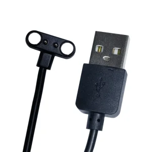
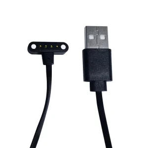
Custom 2 pin Pogo Pin Charger Cable

Custom 2 pin Pogo Pin Black Charger Magnetic USB Charging Cable

Explore Specifications →
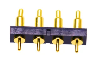
High-Quality standard regular spring pin

High-Quality Standard Regular Spring Pin Series Manufacturer

Explore Specifications →
OEM DIP Spring Loaded Pogo Pin Socket

OEM DIP Spring Loaded Pogo Pin Socket Manufacturers, Suppliers

Explore Specifications →
Custom 8 Pin Magnetic Pogo pin USB C Connector

Custom 8 Pin Magnetic Pogo pin USB C Connector Manufacturer

Explore Specifications →
Cheap 4 pin Pogo Pin Magnetic Charging Cable

Cheap 4 pin Pogo Pin Black Magnetic Charging Data USB Charger Cable

Explore Specifications →
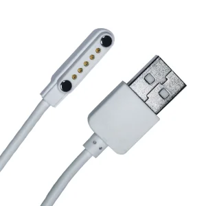
ODM 6 pin Pogo Pin Magnetic Charging USB C Cable

ODM 6 pin Pogo Pin White Magnetic Charging Data USB C Charger Cable

Explore Specifications →
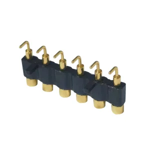
ODM 6 pin Pogo Pin Connector Bending Type

ODM 6 pin Pogo Pin Connector Bending Type PCB Socket

Explore Specifications →
ODM High Current Pin Supplier

ODM High Current Pin Supplier, Engineering Grade Contacts

Explore Specifications →